Flow Calibration Facility
Design, Engineering & Turnkey Delivery
A calibration lab is not a procurement decision.
It is a measurement-integrity decision.
We design, engineer and commission complete flow meter calibration facilities — from concept through ISO/IEC 17025 compliance and NABL accreditation. Our facilities provide legally traceable, audit-ready calibration of industrial gas meters, built on the master-meter principle using Coriolis, turbine or ultrasonic reference standards, at operating conditions representative of actual service.
We design, engineer and commission complete flow meter calibration facilities — from concept through ISO/IEC 17025 compliance and NABL accreditation. Our facilities provide legally traceable, audit-ready calibration of industrial gas meters, built on the master-meter principle using Coriolis, turbine or ultrasonic reference standards, at operating conditions representative of actual service.
Why an in-house Calibration facility matters
From gas extraction through transmission & transportation, from local distribution companies to the end users, the accuracy of flow measurement directly determines revenue, regulatory compliance and network integrity. Every custody-transfer meter must be periodically verified against a traceable reference standard — and that reference standard must itself carry a documented, defensible uncertainty chain back to a national measurement institute (NMI).
An in-house calibration facility gives the operator full control of that chain: meters can be verified at actual operating pressure and with the actual medium, eliminating the uncertainty introduced by calibrating at atmospheric conditions and correcting with equations of state. PNGRB regulations in India require traceable, auditable measurement at every custody-transfer point; an NABL-accredited in-house lab is how a CGD company stands audit-ready at all times rather than depending on third-party calibration slots.
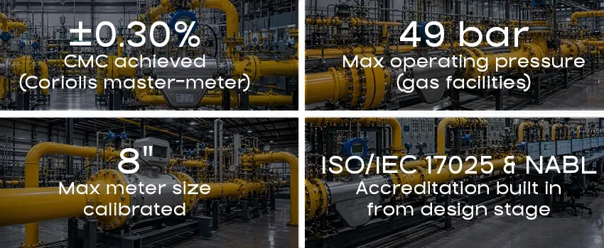
The engineering challenge is to achieve gas-meter-grade measurement uncertainty — typically ±0.3% to ±1.0% (k=2) depending on meter type and operating conditions — in a permanently installed, fully automated facility that can be operated by trained metrological staff, not specialist calibration engineers. That requires precise control of three interdependent parameters: flow rate, static pressure, and temperature — all stable to metrological tolerances simultaneously at the meter under test.
Two engineering approaches
matched to your meter technology
The choice of test medium and reference meter technology is the foundational design decision. It determines the pressure system, the traceability chain, the achievable uncertainty, and the meter types that can be calibrated. We engineer both approaches, and can design hybrid facilities that serve both.
Approach 1
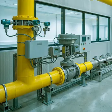
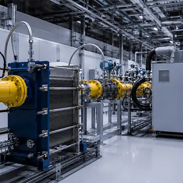
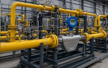
Compressed air at line pressure (typically 10–25 bar) is recirculated through a closed loop by a high-pressure blower. Temperature is conditioned by a precision thermostat heat exchanger upstream of the test section. Two Coriolis meters in series serve as the primary reference standard, providing direct mass flow measurement independent of gas composition, pressure or temperature — the highest achievable accuracy for a master-meter facility.
Air as test medium eliminates gas-safety infrastructure requirements, significantly reducing civil and ATEX costs. The Coriolis reference traceability path (mass → force → time) is the simplest and most robust available. This approach is ideally suited to calibrating mass flow meters intended for CNG dispensing, custody transfer on small-to-medium lines, and meter verification in CGD networks.
- Test medium : Compressed air, closed loop
- Typical pressure range : 10 – 25 bar(g)
- Typical flow range : 50 – 5,000 kg/h
- Achievable CMC : ±0.25 – 0.50% (k=2)
- Reference standard : Dual Coriolis in series
- Temperature control : ±0.05 K at test section
- Gas safety classification : Non-hazardous — no ATEX required
Meter types calibrated
- Coriolis (DUT)
- Thermal mass
- Vortex
- Differential pressure
Approach 2
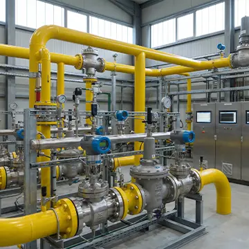
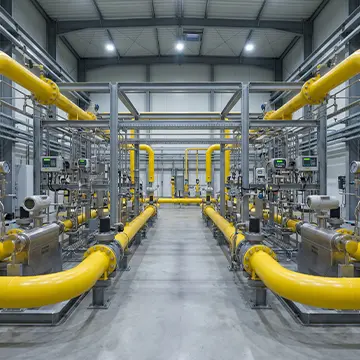
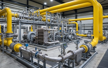
Natural gas — the actual service medium — is circulated at variable pressure through a closed loop by a gas-rated recirculation blower or compressor. Multiple parallel reference meter lines (typically turbine or ultrasonic meters) cover the full flow range, with individual lines activated by automated isolation valves. AGA-8 / GERG-2008 real-gas equations are applied in the data acquisition system for volume correction to reference conditions.
Calibrating volumetric meters on the actual service gas, at operating pressure and temperature, eliminates the principal source of systematic error in gas meter calibration: the deviation between air-calibrated performance and real-gas performance. This approach is required for OIML R 137 and ISO 17089 compliance on custody-transfer grade turbine and ultrasonic meters.
- Test medium : Natural gas, closed loop
- Typical pressure range : 2 – 50 bar(g), variable
- Typical flow range : 4 – 2,500 m³/h (at line conditions)
- Achievable CMC : ±0.3 – 1.0% (k=2, meter dependent)
- Reference standard : Multiple parallel turbine / ultrasonic lines
- Gas property calculation : AGA-8 / GERG-2008
- Gas safety classification : ATEX Zone 1 / IEC Ex
Meter types calibrated
- Turbine gas meters
- Ultrasonic meters
- Rotary displacement
- Diaphragm meters
Engineering fundamentals
The parameters that define metrological performance
A calibration facility is only as good as the stability of its operating conditions at the test section. Uncertainty budget analysis must show that contributions from flow, pressure and temperature instability are small relative to the target CMC. These three subsystems define the engineering challenge.
Flow stability & control
A dedicated flow control valve (FCV) with PID control on the master-meter signal maintains steady flow to within ±0.1% of setpoint. Pulsation damping and adequate upstream straight lengths eliminate velocity profile distortion at the DUT.
Pressure stability & control
A back-pressure control valve (PCV) between the reference section and DUT inlet holds line pressure to ±0.05 bar, automatically compensating for flow-dependent pressure drop across the reference meters. Self-acting PRVs provide coarse pressure stepping.
Temperature stability & control
A bidirectional thermostat bath circulating through a brazed-plate heat exchanger, controlled via external Pt100 cascade with the sensor at the test section inlet, achieves ±0.05 K stability. At 20 bar, unconditioned pressure fluctuations alone can introduce temperature-equivalent errors exceeding the CMC target via Joule-Thomson effects.
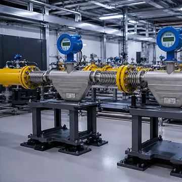
Vibration isolation
In-series Coriolis reference meters are mounted on independent supports with SS bellows flex connections, physically separated and with perpendicular oscillation plane orientation and electrical signal isolation to prevent cross-talk between adjacent meters.
Reference meter architecture
Dual in-series or multiple parallel reference lines provide cross-validation between reference standards, redundancy against single-point failure, and coverage of the full measurement range with optimised uncertainty at each flow point.
Uncertainty budgeting
Full ISO GUM uncertainty evaluation covering reference meter accuracy, pressure and temperature measurement, gas property calculation (AGA-8/GERG-2008 for gas, CIPM for air), settling-length effects, and DAS resolution — computed at design stage, not after commissioning.
Scope of work
What we deliver — full EPC
We take full project responsibility from concept through hand-over, with a single point of accountability across all engineering disciplines. Each facility is custom-engineered to the specific operating envelope, meter technology and accreditation target.
Concept & process design
PFD, P&ID, ISO GUM uncertainty budget, reference meter selection, flow range partitioning, settling-length and hydraulic analysis.
Detail engineering
Mechanical, instrumentation, electrical and control system design. Vibration isolation, thermal analysis, pressure vessel and piping per PED.
Procurement & supply
Specification and sourcing of compressors, blowers, heat exchangers, control valves, Coriolis / turbine / ultrasonic reference meters and instrumentation.
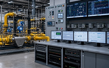
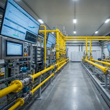
SCADA & automation
PLC / SCADA / DAS with automated calibration sequencing, multi-point test execution, condition monitoring and calibration certificate generation.
Commissioning & qualification
CMC verification, repeatability and stability testing, ISO 17025 documentation package, NABL accreditation support structured from design stage onward.
Project execution
How a facility comes to life
Six structured phases — metrology leads every decision, from the first uncertainty calculation to the final accreditation document.
Flow range, operating pressure, test medium, meter technology, CMC target and NABL / ISO 17025 obligations are defined. The ISO GUM uncertainty budget is established before any design begins — it drives every subsequent engineering decision and equipment selection.
Process flow diagram, control philosophy, hydraulic and thermal modelling, reference meter line architecture, ATEX area classification (if gas medium), CAPEX estimate and risk register.
Full P&IDs, equipment data sheets, instrument index, electrical single-lines, settling-length calculations, vibration isolation layout, vendor package specifications and civil / structural interface drawings.
Competitive tendering, vendor qualification, factory acceptance testing (FAT) of reference meters, critical instrumentation and control packages before site delivery.
Site supervision, mechanical completion checks, loop checks, cold and hot commissioning. Stability, repeatability and linearity runs to demonstrate metrological performance across the full flow range before hand-over.
Calibration procedures, measurement uncertainty statements, quality manual inputs, instrument traceability records, inter-laboratory comparison protocols and a complete audit-ready documentation package structured for NABL submission and ongoing surveillance.
Why Eximp Measurement
The difference between a test bench and a calibration facility
The difference is the metrology behind it. Our capability was built through real project delivery on national-scale calibration infrastructure — not claimed on paper.
Metrology-first engineering
NABL / ISO 17025 built in from day one
Accreditation requirements are embedded in the design, not retrofitted. Documentation, traceability chain and quality records are structured for audit readiness from the outset.
Proven India gas sector track record
PNGRB-regulated custody transfer and calibration infrastructure for CGD operators — we understand the technical requirements and the regulatory landscape that gas utilities face.
Cooperation with European Metrology Institutes
Design and installation are vetted through recognised European national metrology institutes (PTB, VSL), providing an internationally traceable technical foundation for NABL accreditation.
Fully automated calibration workflow
PLC / SCADA / DAS with automated sequencing, condition monitoring and certificate generation — minimising operator dependency and eliminating manual transcription errors in calibration records.
International technology, local execution
EPC delivery experience on European-designed calibration infrastructure in India — bringing world-class metrological standards to local project execution, procurement and supply chains.
Standards & compliance
Regulatory & metrological framework
Facilities are designed and documented for compliance with international and national standards governing legal metrology, custody transfer, uncertainty evaluation and pressure equipment safety.
0
ISO/IEC 17025
0
NABL accreditation
0
ISO GUM
0
OIML R 137
0
ISO 17089
0
AGA-8 / GERG-2008
0
AGA-9
0
PNGRB regulations
0
PED 2014/68/EU
0
IS 5456
0
ATEX / IEC Ex
Planning a calibration facility?
We engage from early concept — uncertainty budget first, engineering second.
Registered Office
426, Mandakini Enclave, Alaknanda,
New Delhi, India – 110019
Contact : +91 11 45686122
Email : empl@eximpmeasurement.com
Operations Office
4- Lotus, Sector No. 24, Plot No. 380,
Nigdi, Pune – 411044
Contact : +91 20 27654694
Email : empl@eximpmeasurement.com
Sales Office
145/146, Sector 10, Bhosari Industrial Area, MIDC, Pune, Maharashtra, India – 411026
Contact : +91 20 27655952
Email : empl@eximpmeasurement.com
Projects
3 / 17, Sangath Bunglows,Off Sama Savali road, Vadodara, Gujarat, India – 390008
Contact : +91 9011932007
Email : empl@eximpmeasurement.com
© 2026 EXIMP
Design Made by Eximp Measurement Private Limited


ISO GUM uncertainty is computed at design stage. Component selection, settling lengths and reference line architecture are driven by the CMC target — not the other way around.